You may wish to refer to the Part 1 shopping list post.
So we have this little esp8266 thing; it's supposed to connect to WiFi. But how do we do that? Well one way is to use a programmer device to connect to it and tell it what to do. This is a nice solution (and one which I will explore at a later date). But in the interest of getting started cheaply, we don't have a programmer. We do have an Arduino. And as that's what we're going to be using it with anyway, we may as well use that to control it right through.
To step through this, I've taken a brand-new out of the packet esp8266. Everything I experience, you will experience.
So firstly, what we should be doing here in terms of wiring. We need to know the pinout of the esp8266. I made this lovely diagram which I've got stuck on a whiteboard near my desk while I'm working. A bit of Googling found it, then I drew it special for you!
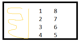
- Rx
- GPIO 0
- GPIO 2
- Gnd
- Tx
- CH-PD
- RST
- Vcc
We need M-F jumpers to wire most of this up. On my breadboard I've got a 3.3v power supply at one end with + and - stuck in the corresponding rails, and the Arduino at the other end. More on the 3.3v later! The hardest thing is rotating your diagram and the actual esp8266 the right way - I kept spinning mine or having it with the pins facing up!
- Pin 4 to - rail on the breadboard
- Pin 8 to the + rail on the breadboard
- Pin 6 to a line on the breadboard, then a 10kΩ resistor from that line to the + rail
- Pin 5 to digital pin 2 (D2) on Arduino
- Pin 1 is the tricky one. First we use an M-F jumper to put it to a space on the breadboard. Then we have a 2.2kΩ resistor between that line and the - rail. This I believe drags it down to 0v to stop it floating when there is no signal. Then we need a 2.2kΩ resistor from the same line to a new line, and finally a M-M jumper to the pin 3 (D3) on Arudino.
- A M-M jumper from Arduino ground to the - rail
I know number 5 sounds squiffy - it's really not that difficult. Hopefully the circuit I show below should help. The resistor to the - rail stops the voltage floating when not in use (which can cause problems) and is, I believe, called a pull-down resistor. The other resistor is, I assume, a voltage divider and is, again I assume, because the Arduino can output 5v and more than 3.3v can make the esp8266 stop working. It may - and probably will - work if you just go straight through. But then it may not.
At this point I must add I didn't have the right resistors, so used a 2kΩ in place of 2.2kΩ and two 470Ω in series in place of the 1kΩ. They're close enough and seem to be ok!
It's also worth noting that if you have a different Arduino you can probably connect through to one of the other Serial lines. The Nano only has one which will be in use by the Arduino/PC connection. So figured may as well use SoftwareSerial to do it for us. I believe it's slower, but it's what the rest of the tutorials will be doing, and it's fast enough. I wanted something that should work for everyone.
Hopefully this tinkercad diagram will help make that all clear.
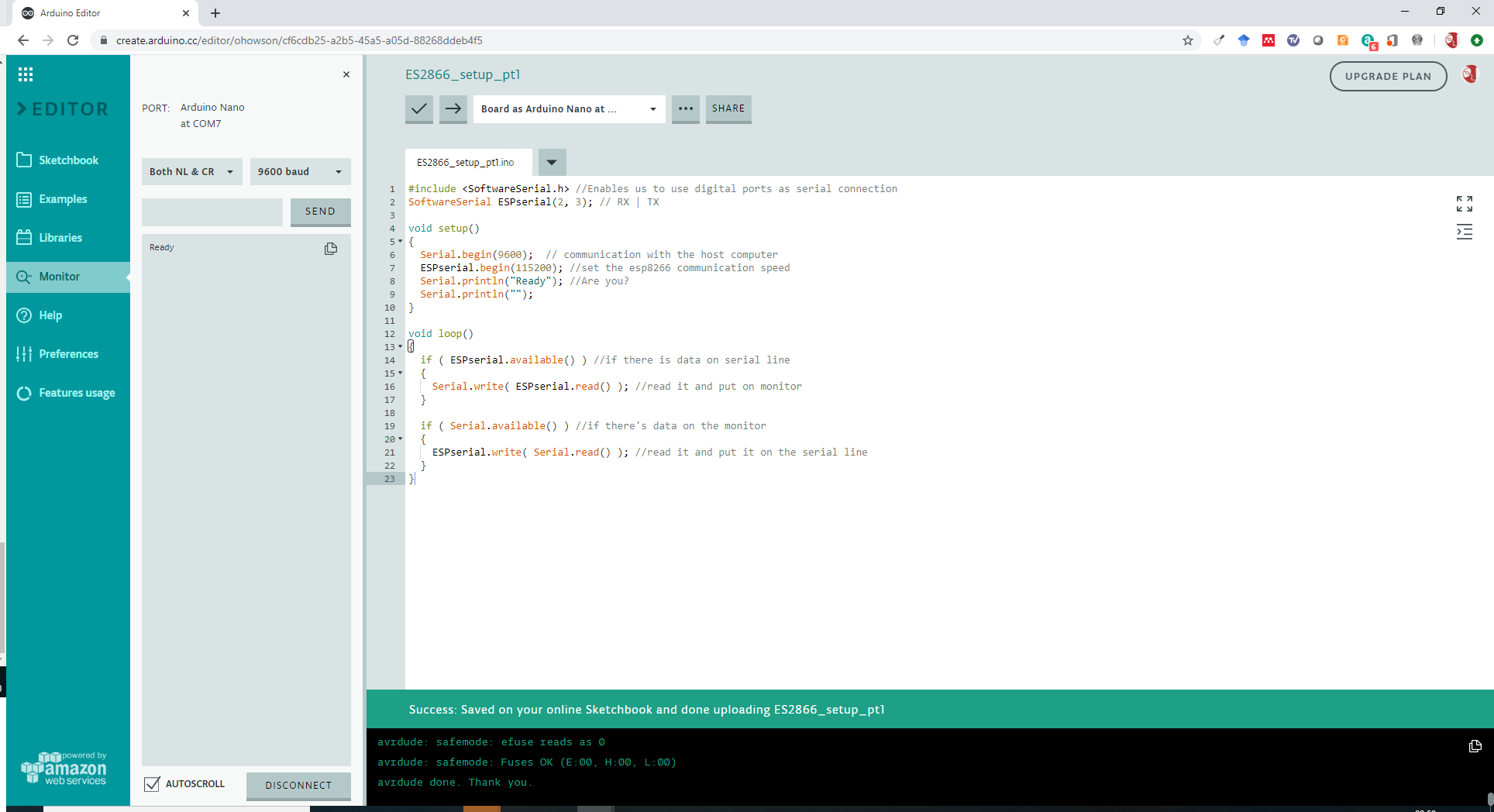
Now for the code; I've been using the Arduino web editor though the same should work on an installed version.
#include <SoftwareSerial.h> //Enables us to use digital ports as serial connection
SoftwareSerial ESPserial(2, 3); // RX | TX

void setup()
{
  Serial.begin(9600);  // communication with the host computer
  ESPserial.begin(115200); //set the esp8266 communication speed
  Serial.println("Ready"); //Are you?
  Serial.println("");
}

void loop()
{
  if ( ESPserial.available() ) //if there is data on serial line
  {
    Serial.write( ESPserial.read() ); //read it and put on monitor
  }

  if ( Serial.available() ) //if there's data on the monitor
  {
    ESPserial.write( Serial.read() ); //read it and put it on the serial line
  }
}
Now how to get that on to the Arduino? This is always a bit of fun. I prefer to use the web-based developer at on the Arduino website though you might want to download and use the offline one. Either copy and paste, or type in (my preference - you learn more) that code. I've linked to the sketch here.
- Power on your 3.3v to fire up the esp8266
- Plug your Arduino into the computer
- At the top, you need to choose the board. I chose the **Arduino Nano** (I knew that bit) then fiddled with the options until I got the right one (mine is using the old bootloader and COM7).
- (If you've not used your Arduino before you may want to try this code which just blinks the in-built LED slowly. I use this rather than the standard 'blink' code as that sometimes comes built in and you don't know if yours has worked or not!)
- On the left hand side of the screen, under >EDITOR there is a Monitor button - click that so you can see what the Arduino is doing. In the left hand dropdown choose Both NL & CR (this uses \r\n as a line terminator which is what the ESP8266 uses) and select 9600 baud in the other one - this is the speed we have told the Arduino to communicate with the computer at.
- Now press the right arrow to upload (hopefully) to your Nano.
- Hopefully the avrdude will say 'done. Thank you.' and in the monitor window it will say 'Ready'
Mistakes I made (in the interest of honesty) I originally used an alternative connection having the reset pin high and the CH_PD to D4 but that didn't work (probably because my program didn't match!). I also forgot to ground the Arduino...
Now let's have a play with this ESP8266 and see whether we can get it to work?
If you type in:
AT and hit Enter
The ESP8266, via the Arduino, should return OK
It may or may not also return a bunch of gibberish. My first one did because it couldn't cope with the communication speed (or maybe the Arduino couldn't I don't know), my second one oddly didn't. Either way we will tell the ESP8266 to reduce down to 9600 baud which we know will work.
AT+UART_DEF=9600,8,1,0,0 and hit Enter
Now we need to adjust the code - change line 7 to read 9600 - I've linked to the updated code here.
Reflash and enter AT again to make sure everything is still Ok.
Let's make sure we can connect to the WiFi shall we?
Enter these commands:
AT+CWMODE=1
This sets the mode to 1 meaning it will act as a station (client). You should get OK back.
AT+CWLAP Gets a list of networks the ESP8266 can see. For example I can see:
+CWLAP:(3,"SHELL 1567AF",-84,"a4:91:b1:15:67:af",6,53)
+CWLAP:(4,"GDog",-41,"48:8d:36:1d:8a:cf",11,56)
+CWLAP:(3,"PLUSNET-T6TJ",-78,"b8:ee:0e:f0:7a:04",11,28)
In the barackets the first number is the type of security, SHELL and PLUSNET use WPA2 and PSK, GDog uses WPA, WPA2 and PSK. Then there's the names, and finally the MAC address of the access point.
AT+CWJAP="YOUR_SSID","YOUR_PASSWORD" connects to the WiFi network with the given SSID (network name) and password.
When I ran this I got:
WIFI DISCONNECT
WIFI CONNECTED
WIFI GOT IP

OK
Which is fairly clear, it disconnects if relevant, reconnects, gets an IP address and then say's all is OK.
Finally:
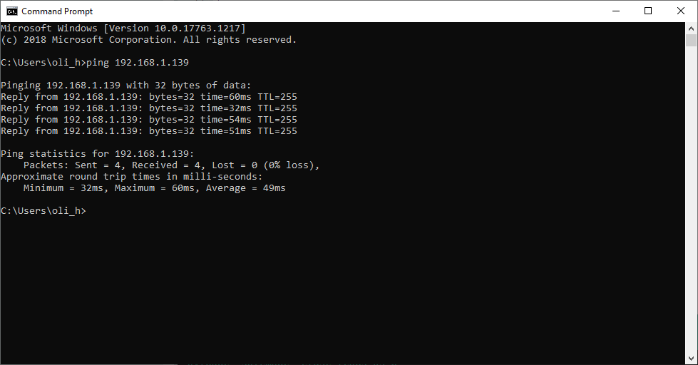
AT+CIFSR Get's and reports the IP address and MAC address of the ESP8266. I got:
+CIFSR:STAIP,"192.168.1.139"
+CIFSR:STAMAC,"5c:cf:7f:49:d4:ca"
And to prove this worked, I can open up a terminal/command line on my PC and ping that address:
A useful list of known AT commands for the ESP8266 is available here.
And that's pretty much us; we've successfully connected the ESP8266 to WiFi, via our Arduino (the cheapest one available not an expensive Mega or Uno or anything) and can move on to the next tutorial. Whoo.