You may wish to refer to the Part 1 shopping list post.
The next tutorial is going to be looking at reporting a button state on the web server we built in part 3. First though, we're going to make sure we can build a button that works! I tend to say button; you may see switch, tactile switch, momentary switch... I like 'button'. Regardless, you're most likely to have ones that look like this:
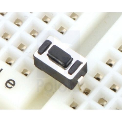
Although I always struggle to remember which of the legs are common and not - I have prefer simple ones like these:
You can remove out the other circuits if you wish and build this one from scratch. I just disconnected the digital pins from the Arduino and left everything else where it was.
The simplest way to build such a circuit would be to have a button with one side
connected to + and one side connected to the digital pin. When the switch is open the pin receives no input (which we call LOW). When the switch is closed, the switch receives input (which we call HIGH). However, there's bit of a problem here in that when the switch is open, it is called 'floating' and can report false values.
Instead what we do is connect one side of the switch to + and the other end to -. However this would cause a short circuit so between the - and the switch we put a resistor - 10k being a common choice (though almost anything around that range will do). We then connect the digital pin (in this case D5) to the switch on the - side.
This is called a pull down resistor. There's nothing special about the resistor, it's a normal resistor that serves a purpose. Having the digital pin connected to - normally (via the resistor) means it is held to 0v - it reports a consistent low. Closing the switch allows the +'ve current to flow through the switch, and as it's easier for the current to go to the digital pin than force it's way through the resistor to ground, that's the route it takes and we get a consistent high signal. There are also pull-up resistors which do the same thing but hold the signal high and closing the switch drags it low. For this system the choice is purely arbitrary.
For power you could connect to the +3.3v (or even +5v) of the Arduino and run the - from ground on the Arduino. However, this would not be what we want for the next part of the project so we instead will connect the +/- rails to a 3.3v supply from elsewhere and just connect the Arduino ground to the - rail.
I've drawn the circuit out for you here.
Now for the code. We could just have the LED light up when the button is pressed and out when not, but I like to go a bit overboard so the code below has the LED (I used the built in LED) flash fast if the button is HIGH (closed) and slowly if it is LOW (open). I also have it output the value (as 1 or 0 accordingly) on the serial monitor.
const int buttonPin = 5; //We will use D5 as the pin reading button

void setup() {
  pinMode(LED_BUILTIN, OUTPUT); //Open up the built in LED for output
  pinMode(buttonPin, INPUT); //Open up the chosen pin for input
  Serial.begin(9600); //Use the serial monitor
}

void loop() {
    Serial.print(digitalRead(buttonPin)); //Ouput the current state of the button to the monitor
    if (digitalRead(buttonPin) == HIGH) {  //If it's high/closed
      digitalWrite(LED_BUILTIN,HIGH);
      delay(100); //flash fast
      digitalWrite(LED_BUILTIN,LOW);
      delay(100);
    } else { //or it's low/closed
      digitalWrite(LED_BUILTIN,HIGH);
      delay(500); //flash slow
      digitalWrite(LED_BUILTIN,LOW);
      delay(500);
    }
}
Give it a try. Next we will look at combining the button press to and the web server.