You may wish to refer to the Part 1 shopping list post. You may also wish to refer back to Part 3 and Part 4a of this series.
So this section really is just a combination of the previous two parts. Firstly we add the button circuitry to the existing web server circuit. This means a 10k from one side of the switch, via a jumper wire to the - rail, with another jumper from the same side of the swith do digital pin 5 on the Arduino, then a jumper wire from the other side of the switch to the + rail. This circuit can be seen here.
Then we add a few lines of code;
const int buttonPin = 5; //We will use D5 as the pin reading button goes at the top in the declarations.
pinMode(buttonPin, INPUT); //Open up the chosen pin for input goes in the setup to open up the input pin.
Finally, we adjust the section of loop() to include a check of the input pin value, and output the corresponding response:
    if (connectionId != -1)
    {
      //build the webpage
      String webpage = "<html><head><title>Testing!</title></head>";
      webpage += "<body><h1>Button Check</h1><p>Digital Button 5 is: ";
      if (digitalRead(buttonPin) == HIGH)
      {
        webpage += "High";
      }
      else
      {
        webpage += "Low";
      }
      webpage += "</p></body></html>";
      sendWebpage(connectionId, webpage); //Send the webpage
    }
You can access the whole modified code here if you are too lazy to type it all in yourself.
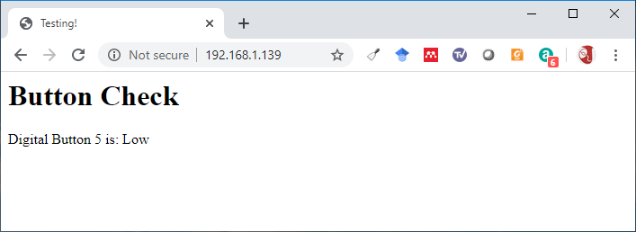
And that really much is it. If you hit the same IP address as before in your browser, you should see (without pressing the button):
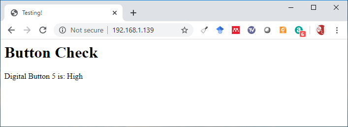
And then if you hold the button and hit refresh:
Now things are starting to get interesting! If you did some port forwarding, you could access that from work and tell if anyone has broken in to your workshop and pressed your button!
In the next section we will start looking at the thing that actually triggered this whole series of tutorials, responding to multiple buttons!